


The condition varied for each of the seven series of simulations was:
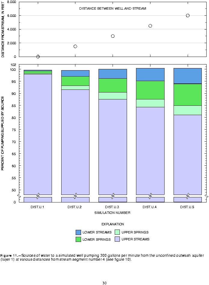
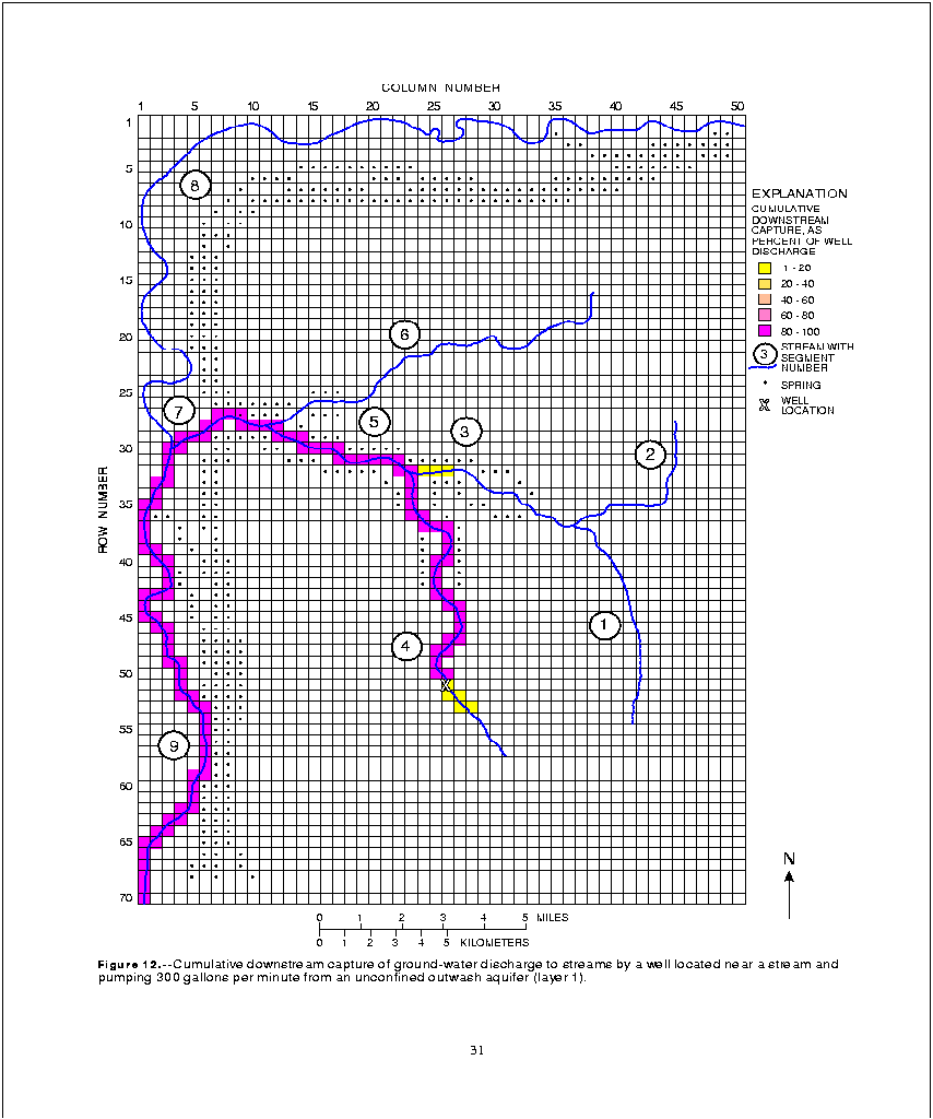
These simulations demonstrate that a well pumping from a highly permeable outwash aquifer near a stream will, at equilibrium, capture most of its discharge from ground-water flow that would have discharged to the stream. With the well nearest the stream (less than 1,500 ft; DIST.U.1), about 98 percent of well discharge derives from capture of discharge to the streams and springs in the upper drift plain (fig. 11). Streamflow was reduced by more than 95 percent of well discharge in most of segment 4 and in all of segments 5, 7, and 9 (fig. 12). When the well is moved away from the stream, a larger percentage of pumping is derived from capture of discharge to the lower streams and springs. However, even when the well is at the maximum distance from the stream (6,000 ft; DIST.U.5), 85 percent of well discharge still derives from ground water that would have discharged to streams and springs on the upper drift plain (fig. 11).
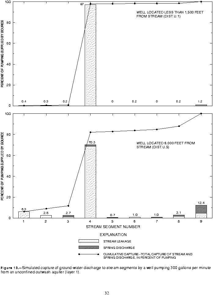
Capture of discharge to streams and springs is shown by stream segment in figure 13. These results show that moving the well from less than 1,500 ft to 6,000 ft away from stream segment 4 reduced capture from that segment from 97 percent to 70 percent of well discharge. Converting these percentages to rates shows that the flow in segment 4 was reduced by 291 gal/min (97 percent of 300 gal/min) when the well was located near the stream, but that the reduction in flow was reduced to 210 gal/min (70 percent of 300 gal/min) when the well was located 6,000 ft from the stream. The decrease in capture from segment 4 was offset by increases in capture from all other stream segments, most notably from segments 1 through 3 (to 11.8 percent of well discharge, an increase of 10.9 percent) and segment 9 (to 12.4 percent of well discharge, an increase of 11.2 percent). The increase in capture from the segments 1 through 3 was mostly discharge to streams, whereas capture from segment 9 was mostly discharge to springs.
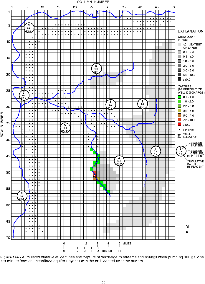
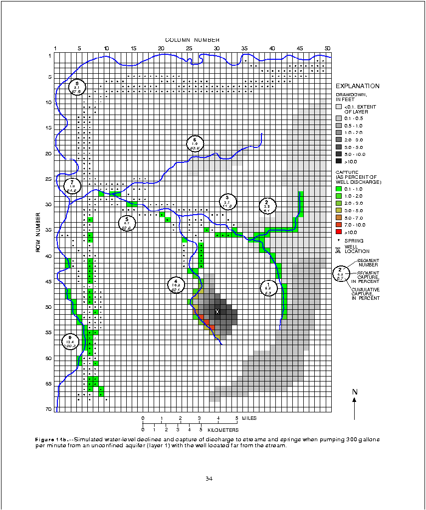
For many simulations, maps showing simulated water-level declines and capture of discharge to individual springs and stream reaches are presented. On these maps, total capture of ground-water discharge to each stream segment and cumulative downstream capture are listed for each stream segment (see fig. 14a). The segment and cumulative downstream captures are expressed as a percentage of the simulated well discharge. At the downstream end of stream segment 9 (where the stream exits the basin), the cumulative capture should be 100 percent for all simulations. In some cases, the cumulative capture is slightly more or less than 100 percent because of rounding errors in the model.
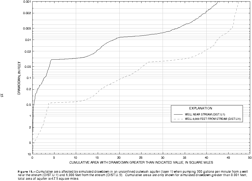
When the pumped well was located near the stream, the effects of the well on stream discharge was highly localized. When the well was located within 1,500 ft of the stream, nearly all well discharge derived from capture of discharge to one stream segment (number 4), and most of the captured discharge derived from the four stream cells nearest the well (fig. 14a). Simulated drawdown was less than 0.5 ft throughout most of the pumped aquifer (fig. 14a). When the well was located 6,000 ft from the stream, the cone of depression of the well must expand more before it captures enough natural discharge from other springs and streams in the basin to offset the discharge of the well. Figure 14b shows that a maximum drawdown of more than 10 ft was simulated in the cell containing the pumping well and that drawdowns of more than 0.5 ft were simulated in many cells. Figure 14b also shows that discharge to streams and springs was affected over a much larger area when the well was located at a greater distance from the stream. Comparison of the cumulative areas affected by simulated drawdown for the DIST.U.1 and DIST.U.5 simulations (fig. 15) confirms that the AOI was much larger when the well was farther from the stream. Simulated drawdown exceeded 0.1 ft over an area of about 21 mi2 in simulation DIST.U.5. However, only about 2 mi2 were affected by drawdowns greater than 0.1 ft when the well was located next to the stream. The stair-step shape of the cumulative-area curves in figure 15 is caused by the discontinuous nature of the uppermost unconfined outwash aquifer.
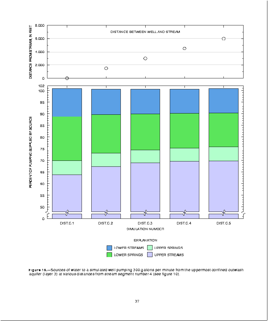
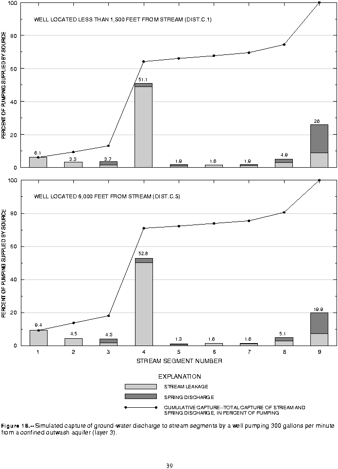
The presence of the low-permeability till between the well and the stream had a significant effect on the source of water to the well. More of the well discharge was derived from capture of flow to the streams and springs in the lower valley in these scenarios than in the corresponding scenarios for the unconfined aquifer (DIST.U). The percentage of well discharge captured from the lower valley streams was nearly constant at about 10 percent in all five simulations (fig. 16). Streamflow was reduced by about 50 percent of well discharge at the mouth of segment 4 (fig. 17). The percentage captured from discharge to the springs in the lower valley ranged from 20 percent when the well was nearest the stream (DIST.C.1) to 15 percent when the well was more than a mile to the east of the stream (DIST.C.5) (fig. 16). Spring discharge on the bluffs was more sensitive to the location of the pumped well than was stream discharge because many of the springs discharge directly from the pumped aquifer (model layer 3).
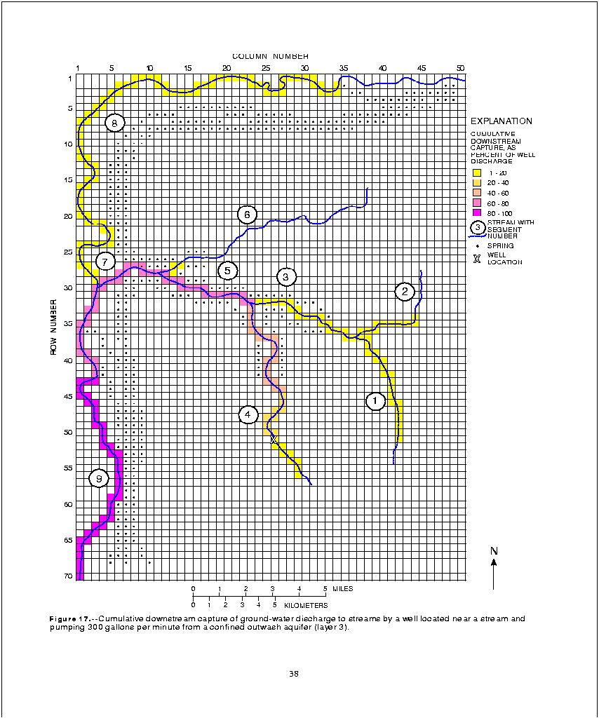
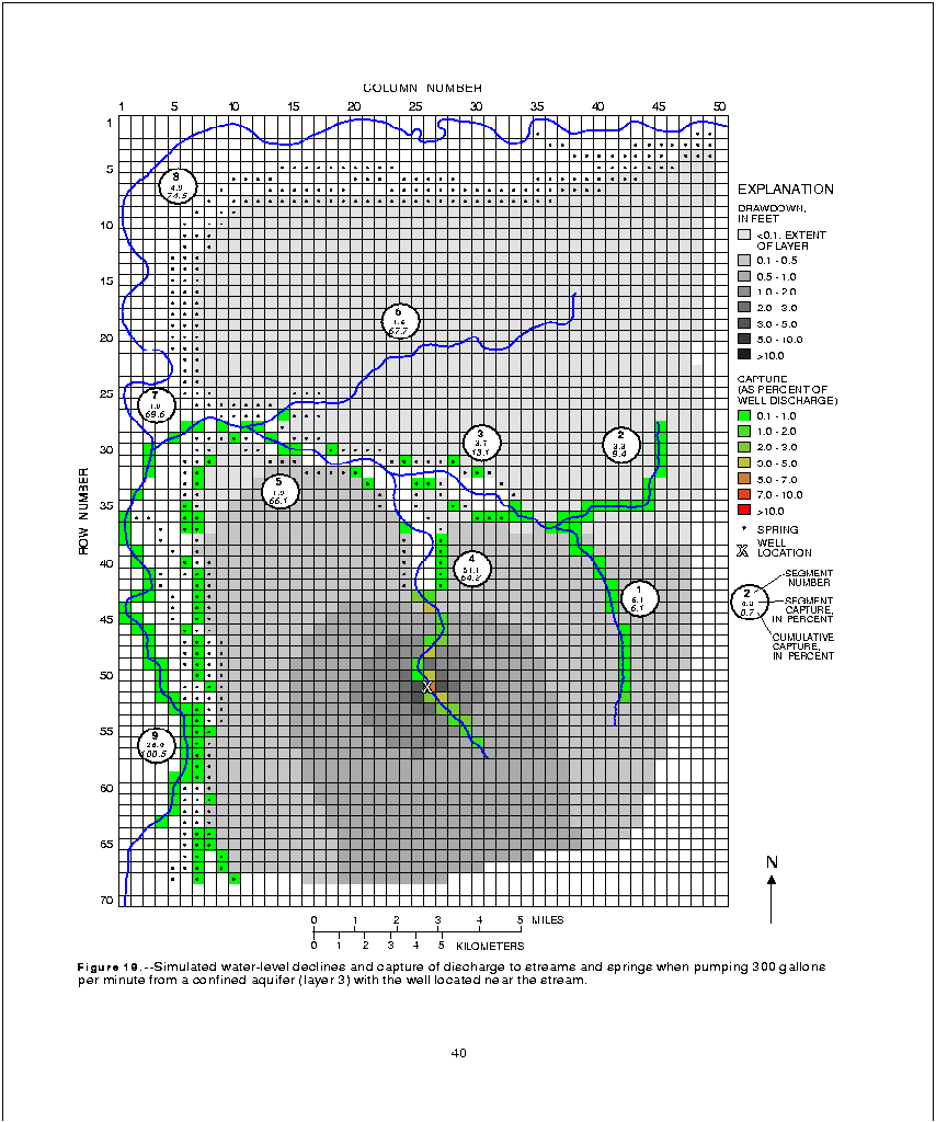
Comparison of simulations DIST.U.1 and DIST.C.1 shows the importance of the till layer in controlling the effect of a well on discharge to streams and springs. When the well pumped from the outwash aquifer directly adjacent to the stream (as in simulation DIST.U.1), about 98 percent of its discharge came from capture of discharge to streams and springs on the upper drift plain. In simulation DIST.C.1, however, a well pumped at the same location from an aquifer separated from the stream by a till layer derived only 70 percent of its discharge from the upper streams and springs (figs. 11 and 16). The effects of the well on the nearest stream reach were even more dramatically attenuated by pumping from the lower aquifer. Comparison of figures 13 and 18 shows that 97 percent of the well discharge in simulation DIST.U.1 was captured from segment 4, while only 51 percent was captured from segment 4 in simulation DIST.C.1. The difference of 46 percent is equivalent to 138 gal/min of the total 300 gal/min of well discharge. The reduction in capture from segment 4 by pumping from the confined aquifer was made up mostly by an increase in capture from segments 1 through 3 (12.3 percent of well discharge) and segment 9 (24.8 percent). Within the range of distances simulated, the distance of the well from stream segment 4 made a small difference in the distribution of capture among stream segments on the upper drift plain (fig. 18). However, because of the direction in which the well was moved, increase in distance from the stream increased capture from segment 1 through 3 and decreased capture from segment 9. Comparison of simulations DIST.U.1 and DIST.C.5 indicates a decrease in capture from segment 4 (44.2 percent of well discharge) offset mostly by increases in capture from segments 1 through 3 (17.3 percent) and segment 9 (18.7 percent).
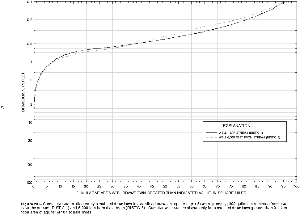
Lateral distance from the stream to the well is less important than the presence or absence of a confining layer between the pumped well and the stream. This is clearly shown by comparing the maps of simulated drawdown and capture of discharge for simulations DIST.U.1 and DIST.C.1 (figs. 14a and 19). The effects of the pumped well were more broadly distributed within the basin when the well pumps from the confined aquifer. Also, the cumulative areas affected by drawdown were much greater for the simulations of pumping from the confined aquifer. For all five of the DIST.C-series simulations, approximately 95 mi2 of the confined aquifer was affected by drawdown of more than 0.1 ft (fig. 20); when the well was placed in the unconfined aquifer, the maximum area experiencing more than 0.1 ft of drawdown was 21 mi2 (fig. 15).
Capture of natural discharge, expressed as a percentage of the well discharge, was nearly constant among the five simulations (fig. 21). Thus, simulations in this series showed that capture of natural discharge to streams and springs at any point was directly proportional to the pumping rate of the well. This result is, in part, an artifact of the assumptions used in constructing the model. Specifically, the transmissivity of a hydrogeologic layer does not vary with saturated thickness in this model. This simplification was based on the assumption that the saturated thickness would not change significantly due to any hydrologic stress imposed on the model. If the transmissivity of the aquifer layer were to change, then the response of the system would no longer be dependent only on the pumping rate and would not vary linearly with the pumping rate.
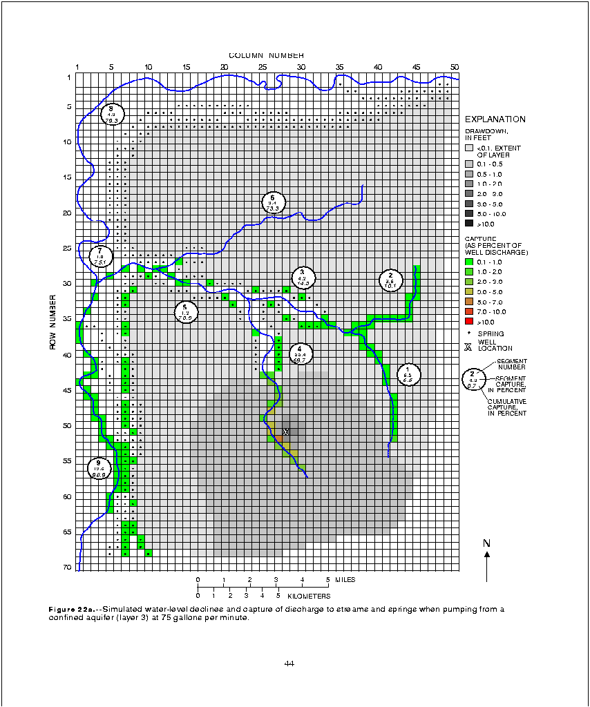
A large number of stream reaches and springs in the lower valley were affected by pumping in scenario PUMP.1 in spite of the low pumping rate of 75 gal/min (fig. 22a). Simulated drawdown in the pumped aquifer was between 2 and 3 ft in the cell containing the well but was less than 0.5 ft over most of the basin.
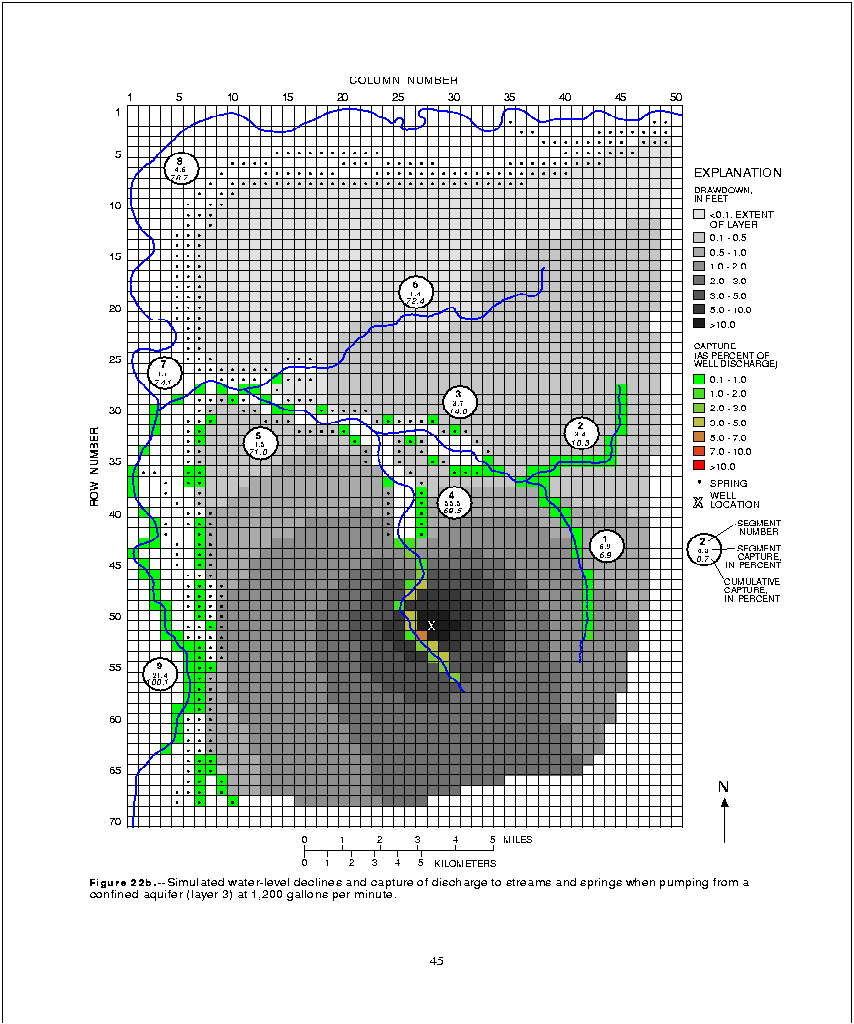
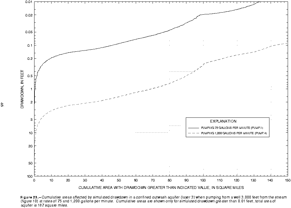
A few additional stream reaches and springs in the lower valley were affected when the pumping rate was increased to 1,200 gal/min (simulation PUMP.4). Also, the shape of the cone of depression of the well began to show the effects of aquifer boundaries at the higher pumping rate (fig. 22b). The effects are greatest to the south and southeast of the well where the cone of depression reached the bedrock boundary; since no flow can be induced across this boundary, drawdown was more severe in this area. The AOI for pumping rates of 75 and 1,200 gal/min were 46 mi2 and 143 mi2, respectively (fig. 23). The effect of boundaries to the aquifer on the AOI are evident in figure 23, which shows a drawdown anomaly at the point where the cumulative area reached 100 mi2.
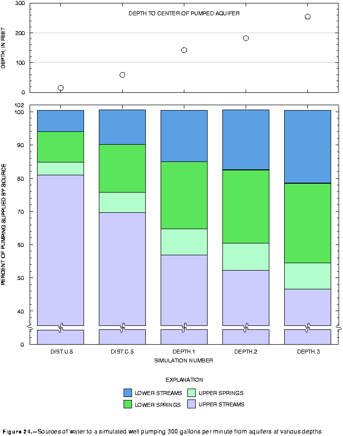
When the well pumped from the unconfined outwash aquifer (model layer 1), 85 percent of well discharge came from capture of discharge to streams and springs on the upper drift plain. Simulation of pumping from successively deeper aquifers at the same location captures successively greater percentages of discharge to streams and springs in the lower valley (fig. 24). Pumping from layer 9 of the model increased the capture of discharge to lower streams and springs from 15 percent to 46 percent (fig. 24), with the increase about equally divided between capture of stream and spring flows. Capture of spring discharge on the upper drift plain also increased from about 4 percent when the well tapped the shallow aquifer to 6 to 8 percent when the well tapped deeper aquifers.
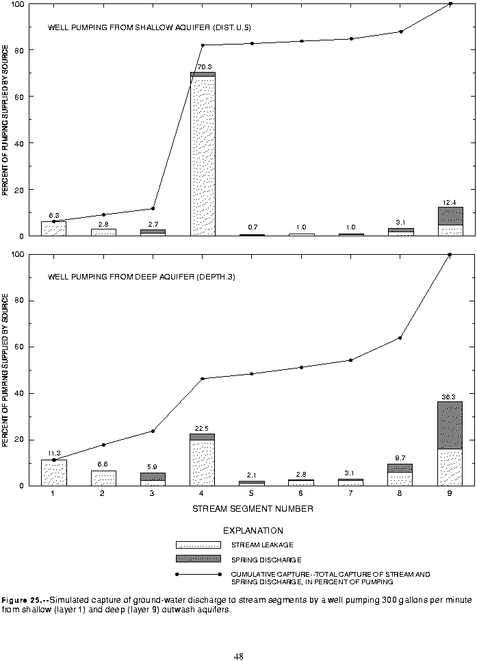
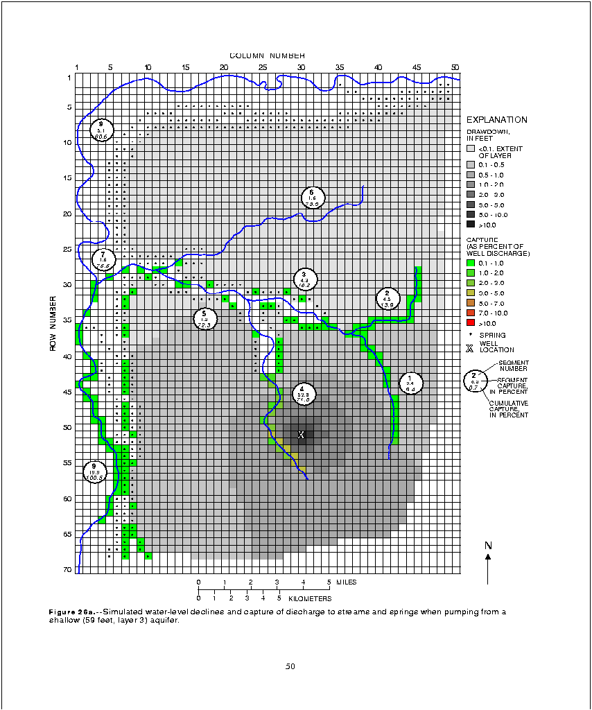
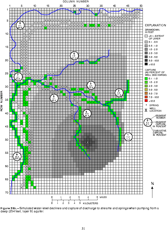
The effect of well depth on natural discharge to streams and springs is even more marked in individual stream segments. The shallow well (simulation DIST.U.5) captured 70 percent of its discharge from stream segment 4 on the upper drift plain and only 12 percent from segment 9 in the lower valley (fig. 25). The deepest well (pumped from layer 9; simulation DEPTH.3) captured only 22 percent of its discharge from segment 4; the decrease of 48 percent (144 gal/min) was partly offset by increases in the capture from segment 9 of 24 percent (72 gal/min) and from segments 1 through 3 of 12 percent (36 gal/min).
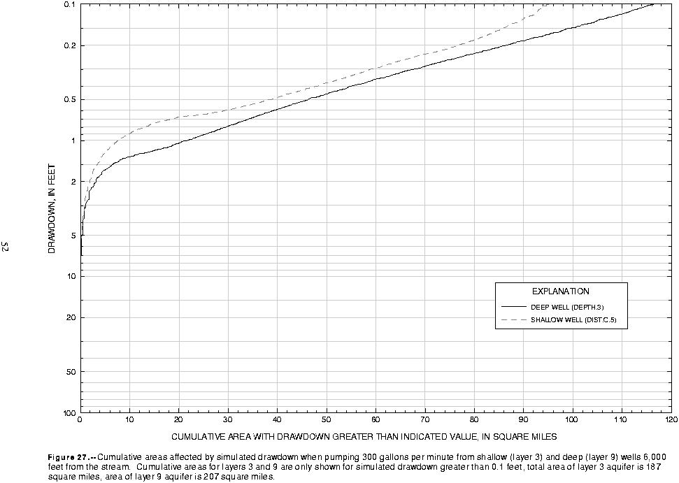
The maps of capture and drawdown for pumping from layer 1 (simulation DIST.U.5, figure 14b), layer 3 (simulation DIST.C.5, figure 26a), and layer 9 (simulation DEPTH.3, figure 26b) show that deepening the well spreads the effects of pumping over a larger area and reduces the magnitude of effects on individual stream reaches and springs. Very few stream reaches or springs contributed more than 1 percent of the water discharged from the pumped well in simulation DEPTH.3, and none contributed more than 2 percent (fig. 26b). The maximum drawdown and cumulative areas of drawdown for wells pumped from layers 3 and 9 are similar; drawdown in the pumped cells was about 10 to 11 ft for each simulation and the AOI ranged from 95 to 116 mi2 (fig. 27).
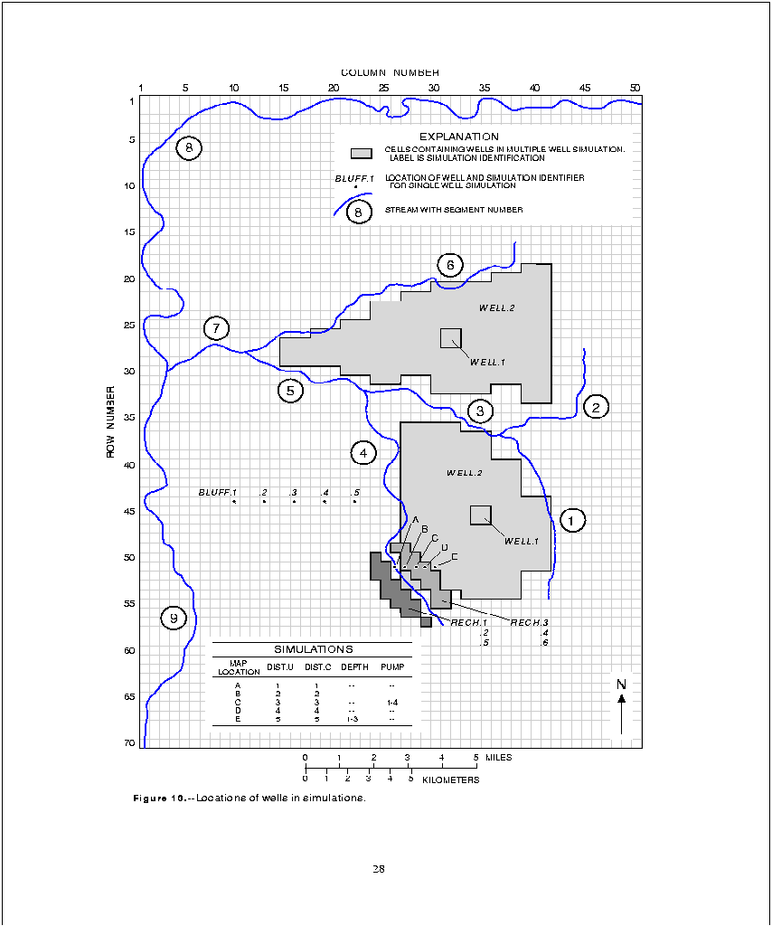
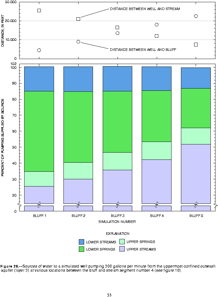
The most obvious effects were on the capture of natural discharge to the springs on the bluff and on the discharge to streams on the upper drift plain. A well placed within 3,000 ft of the bluff (fig. 10) captured 50 percent of its discharge (150 gal/min) from springs on the bluff while capturing only 26 percent from the upper streams (simulation BLUFF.1, figure 28). As the well was moved east from the bluff in successive simulations, the capture from springs on the bluff was replaced by capture from the upper streams. At the location farthest from the bluff (closest to stream segment 4), the percentages captured from springs and from the upper streams were reversed, with about 25 percent coming from the springs on the bluff and 51 percent from the upper streams (simulation BLUFF.5, figure 28). These simulations show that the proximity of the well to discharge areas controls the amount of well discharge derived from capture of ground water that would have discharged to those areas. The percentages of well discharge captured from the lower streams and the upper springs changed little with the distance between the bluff and the well.
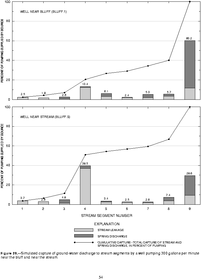
The stream segments most affected in this series were segment 4 on the upper drift plain and segment 9 in the lower valley. Only 30 percent (90 gal/min) of well discharge came from capture from segment 9 when the well was located over 4 mi east of the bluff, but 60 percent (180 gal/min) came from this segment when the well was nearest the bluff (fig. 29). Most of the 30-percent increase in discharge to segment 9 that came from moving the well east was offset by the 26-percent decrease in discharge to segment 4 (fig. 29). Had the well been placed in a deeper layer, it is likely that the effects on discharge to springs on the bluff and to streams in the lower valley would have been even more pronounced.
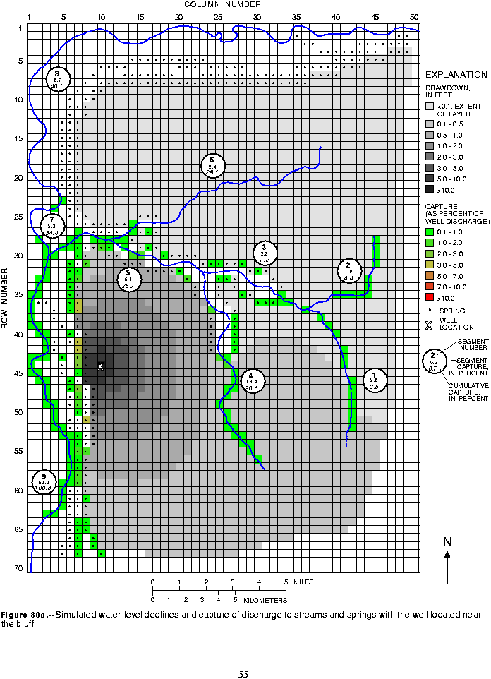
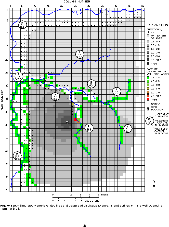
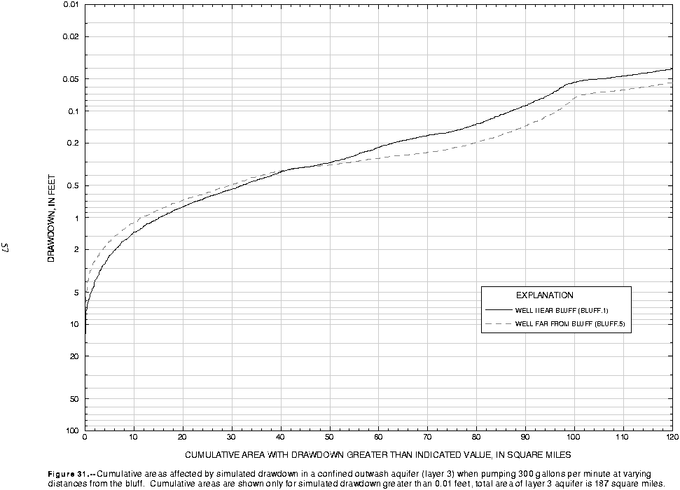
The effect of the distance between the well and the bluff on the cone of depression of the well was minor for this series of simulations. Comparison of the cones of depression for simulations BLUFF.1 and BLUFF.5 (figs. 30a and 30b) indicates that their shapes are affected by the aquifer boundaries, but the overall area and the magnitude of drawdown are very similar for these simulations. The cumulative areas of drawdown shown on figure 31 indicate that simulated drawdown changes little with the distance of the well from the bluff. The AOI for these simulations ranged from 87 to 96 mi2.
In each scenario, it was assumed that 960 new homes were to be built in the basin and that their water needs would be supplied by ground water. The average household water use was assumed to be 450 gal/d (0.312 gal/min). This resulted in an average annual demand of 300 gal/min from ground water. Each model cell covers approximately 52 acres. Twelve acres of each developed cell was assumed to be used for roads and utility right-of-ways, leaving 40 acres available for homes.
The first simulation (WELL.1) assumed a moderate development density of 3 homes per acre. Under this scenario, the 960 homes could be developed within 8 model cells. Each of the 8 model cells contained a separate 40-acre development of 120 homes and each development (cell) had its own well. With a pumping rate of 37.5 gal/min for each of the eight wells, the total pumping in the scenario was
300 gal/min. Four of the developments were clustered in the northern part of the basin and four were clustered in the central part of the basin (fig. 10).
The second simulation (WELL.2) assumed a low development density of 1 home per 20-acre parcel. Under this scenario, the 960 homes were spread over 480 model cells. The homes in this simulation were also divided equally between the northern and central parts of the basin for comparison with simulation WELL.1 (fig. 10). At this density each home would have an individual well for domestic water supply, with no significant pumping for any other water use. The pumping rate for each model cell was
0.625 gal/min and the total pumping for the basin was 300 gal/min. The aquifer developed in each simulation was the uppermost confined outwash aquifer (model layer 3).
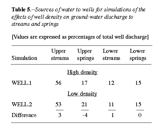
At steady-state, the effect of well density on the capture of discharge to streams and springs was minimal. In both the high and low density pumping scenarios, most well discharge was captured from streams on the upper drift plain (table 5). Streams and springs in the rest of the basin contributed approximately equally, with percentages of captured discharge ranging from 11 to 21 percent. The differences between the sources for these two scenarios was remarkably small; the maximum difference was only 4 percent. Since the centroids of pumping for both simulations were essentially the same, the cone of depression expanded to approximately the same areas in each simulation in order to divert the discharge required to offset the pumping withdrawal.
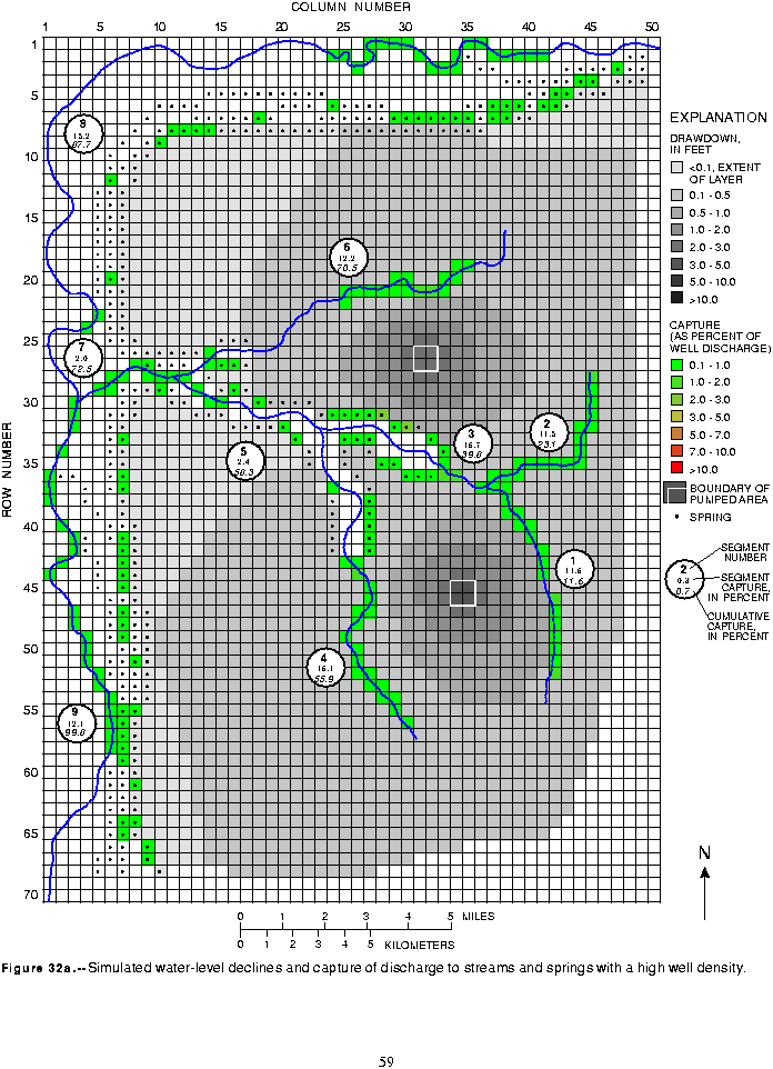
In both simulations, the effects of pumping on natural ground-water discharge rates were spread over broad areas, minimizing the effects on discharge to individual stream reaches and springs. Only a few stream reaches and spring cells contributed more than 1 percent of the total well discharge, and these were all on the upper drift plain with most on stream segment 3 (figs. 32a and b).
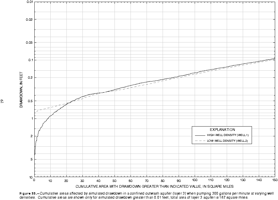
The most noteworthy difference in the effects produced by these two pumping simulations was in the distribution of simulated drawdown (figs. 32a and b). Drawdown of 0.5 ft or more was simulated over an area of 25 mi2 in both scenarios. However, with low density development, the maximum drawdown was only 0.8 ft, compared with a maximum of over 4 ft for high density development. The areas affected by drawdown were essentially equal for drawdown greater than 0.5 ft and the AOI for both simulations was about 145 mi2 (fig. 33).
In some instances, however, natural recharge rates are maintained or even exceeded in developed areas. This generally occurs where household waste water is disposed of in septic systems and cesspools. Another means of increasing recharge rates is to route runoff from impervious surfaces directly into permeable soils through drains, or "drywells", as they are sometimes called. Both on-site waste systems and drywells are efficient means of recharging the ground-water system because water does not have to percolate through the soil zone where it is subject to losses due to plant transpiration and evaporation. Unfortunately, recharge from these sources is often of poor quality and may not be a desirable addition to the ground-water reservoir.
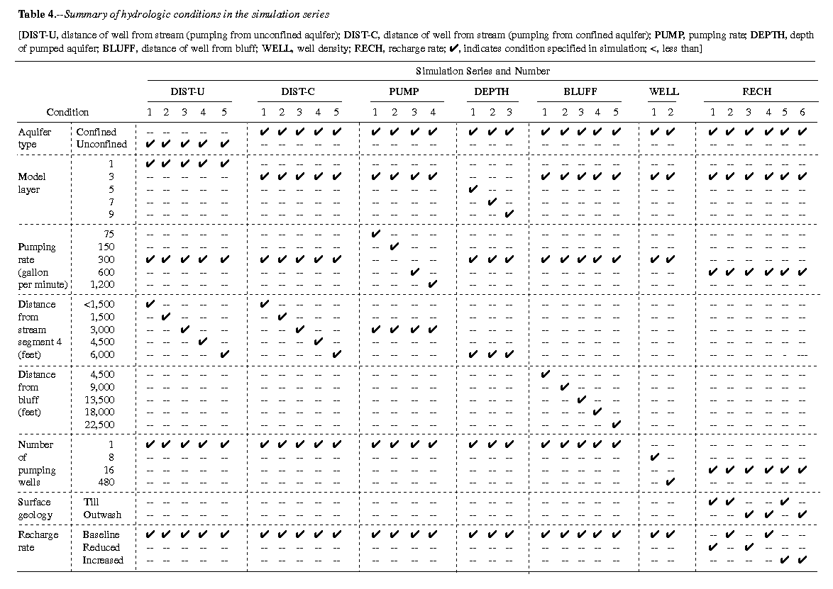
Each of these conditions, reduced and increased recharge, would have an effect on the capture of ground-water discharge to streams and springs by pumping wells. The purpose of the RECH series of simulations was to determine the extent and magnitude of these effects in the hypothetical basin. The term "effective discharge" describes the net withdrawal from the ground-water system resulting from both well discharge and changes in recharge rate caused by development. As an example, if development occurs and a new well withdraws 600 gal/min and recharge is reduced by 300 gal/min because of the increases in impervious surfaces, the effective discharge is 900 gal/min. The term is useful because it allows comparison of scenarios that include both well withdrawals and changes in recharge.
In the RECH series of simulations, it was assumed that moderate density (3 homes per acre) development of 1,920 homes covers an area equivalent to 16 model cells near stream segment 4 (fig. 10). The area is underlain by recessional outwash deposits, and the average annual recharge is estimated to be 27 in/yr. The per-household water use is the same as was assumed for previous scenarios (450 gal/day), and the average annual pumping rate for the development is 600 gal/min; all ground water is withdrawn from the uppermost confined outwash aquifer (model layer 3).
In simulation RECH.3, streets and other impervious surfaces cover 27 percent of the area, and all runoff from these surfaces is routed directly to ditches and is not allowed to recharge the ground-water system. The area has sanitary sewers, and no other measures are taken to enhance recharge, so total recharge is effectively reduced by 27 percent, or the equivalent of about 300 gal/min, from natural conditions. The effective discharge for simulation RECH.3 was approximately 900 gal/min. In simulation RECH.4, the area is served by a sanitary sewer system, but measures are taken to enhance recharge (such as drywells and retention basins) and recharge rates are the same as under natural conditions. The effective discharge for this simulation was 600 gal/min. In simulation RECH.6, recharge enhancement measures are taken and the area does not have sewers. It was assumed that 50 percent of the water requirements of the household move through the septic system to recharge the shallow ground-water system. Thus, for simulation RECH.6, the effective discharge rate was equal to the pumping rate, 600 gal/min, less the 50 percent that returned to the ground-water system, 300 gal/min.
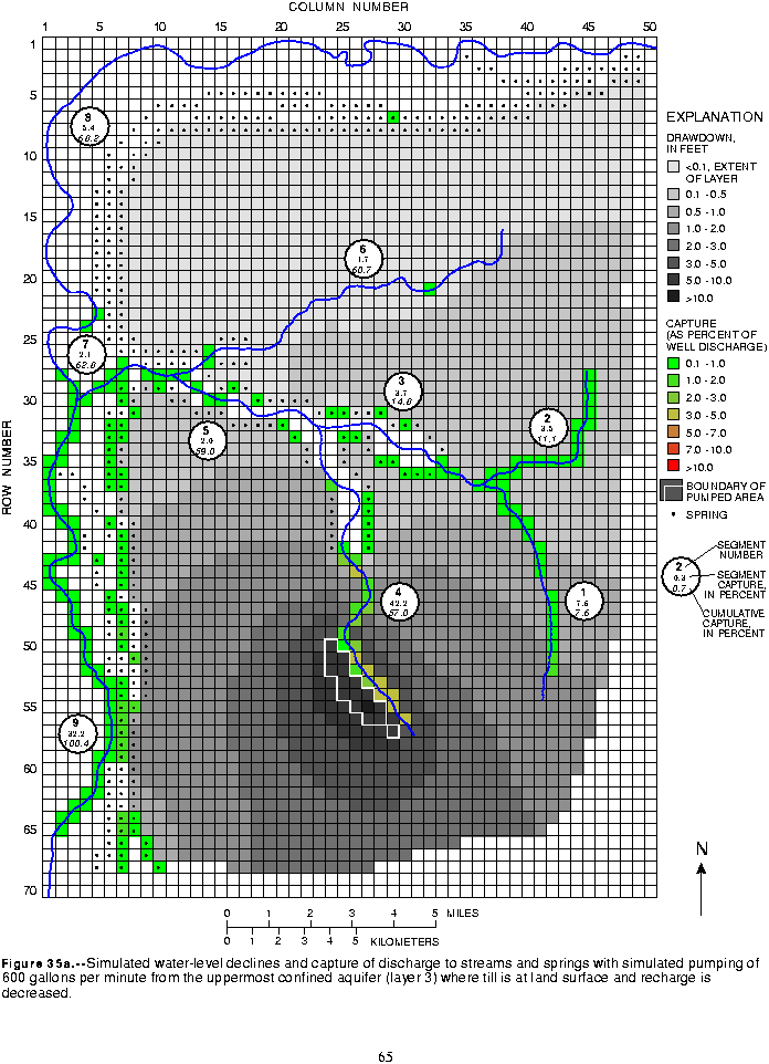
Because the natural recharge rate is highly dependent on the hydraulic characteristics of the surface hydrogeologic layer, three additional simulations (RECH.1, RECH.2, and RECH.5) were made for an area adjacent to stream segment number 4 that is underlain by till (fig. 10) so that comparisons could be made of the effect of the surface hydrogeologic layer. The locations of the wells in the till and outwash scenarios could not be the same; however, they were adjacent and had nearly identical proximity to nearby boundaries (fig. 10). The same assumptions were used regarding the percentages of impervious area and recharge reductions as well as the percentage of domestic water use available for recharge through the septic systems. The conditions for each simulation are summarized in table 4.
In the till-covered area, reducing the recharge of 18 in/yr by 27 percent over the 1.3 mi2 area of development effectively reduced recharge by about 200 gal/min, or one-third of the 600 gal/min well discharge for the development. For simulation RECH.1, the effective discharge was approximately 800 gal/min. In simulation RECH.2, recharge was maintained at the natural rate, so that the effective discharge was equal to the pumping rate of 600 gal/min. The third simulation in the till covered area (RECH.5) had recharge increased by an amount equal to 50 percent of the pumping rate or 300 gal/min; thus for simulation RECH.5, the effective discharge rate was equal to 600 gal/min less 300 gal/min, or 300 gal/min.
The percentages of effective discharge supplied by capture of ground water that would have discharged to streams and springs are shown in figure 34. Within the till area, for the cases of reduced recharge and natural recharge (RECH.1 and RECH.2; fig 34), the percentages of capture from various sources are identical. Although these are percentages of the effective discharge, equal percentages do not represent equal rates of capture. For example, 57 percent of the effective discharge rate was captured from the upper streams in both the reduced (RECH.1) and natural (RECH.2) recharge simulations; because of the difference in effective discharge rates, this represents capture of 456 gal/min from the upper streams in the reduced recharge simulation and capture of only 342 gal/min in the natural recharge simulation (fig. 34). By increasing recharge, as was simulated in RECH.5, an essentially new source of water becomes available to offset discharge from the pumped wells. This additional recharge was added to the water-table layer (layer 2 in this case) while the pumped well discharged from layer 3. The additional recharge resulted in additional downward leakage and additional water available to the wells, streams, and springs at equilibrium.
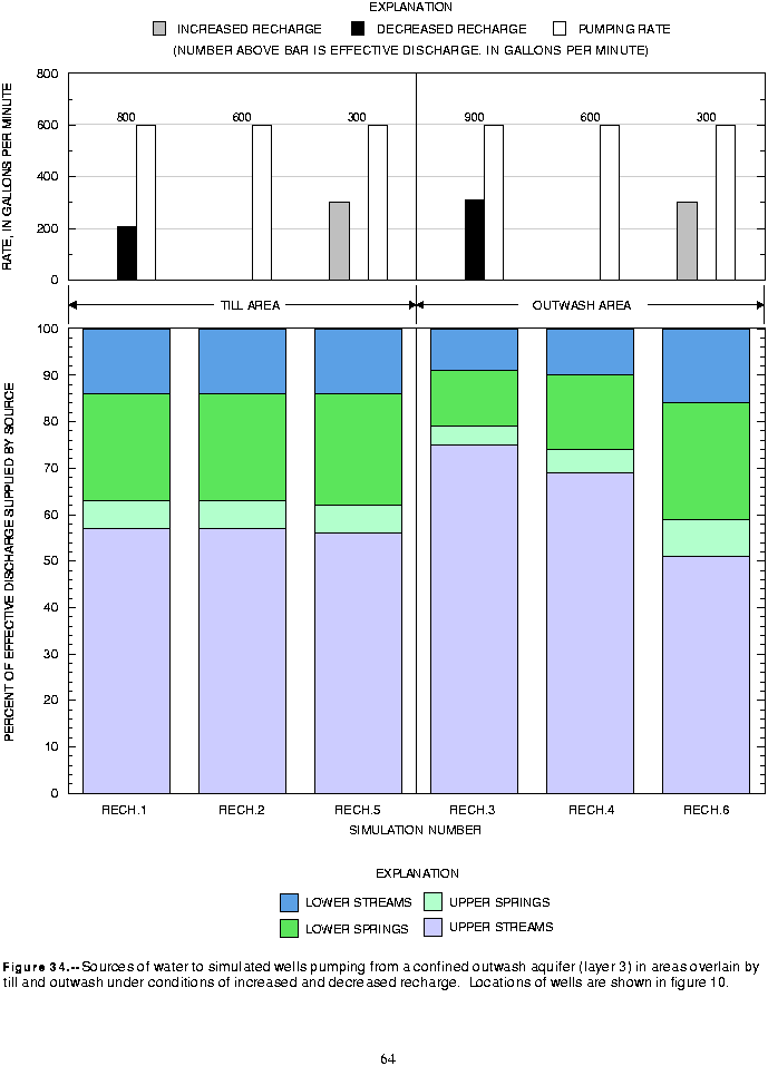
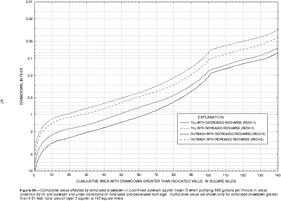
The simulated drawdown distribution in figure 35a reflects the effects of both the well discharge and the reduction in recharge in scenario RECH.1. The cone of depression is elongated parallel to the stream segment with its shape strongly controlled by the boundaries to the aquifer. There are several stream reaches in segment 4 with baseflow reduced by 3 to 5 percent of the effective discharge rate of 800 gal/min. Additionally there are several springs on the bluff above stream segment 9 that have had discharge reduced by 1 to 2 percent of the effective discharge. In contrast, increasing recharge to the till had a noticeable effect on the drawdown distribution and on the percentage of well discharge derived from captured baseflow and spring discharge (fig. 35b). The cumulative areas of drawdown (fig. 36) reveal that, at equilibrium, water levels increase as recharge increases, and accordingly, the size of the AOI decreases from about 133 mi2 for decreased recharge to 97 mi2 for increased recharge.
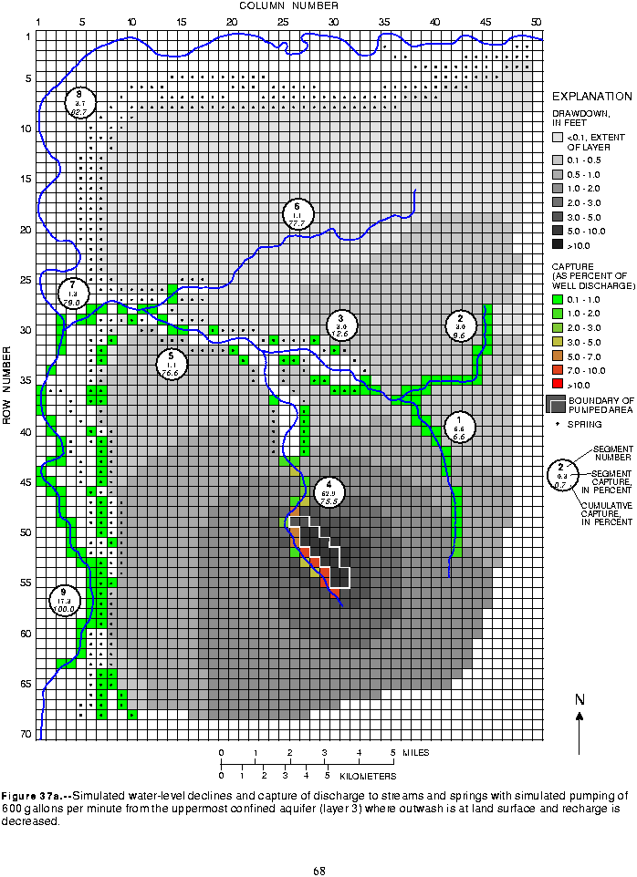
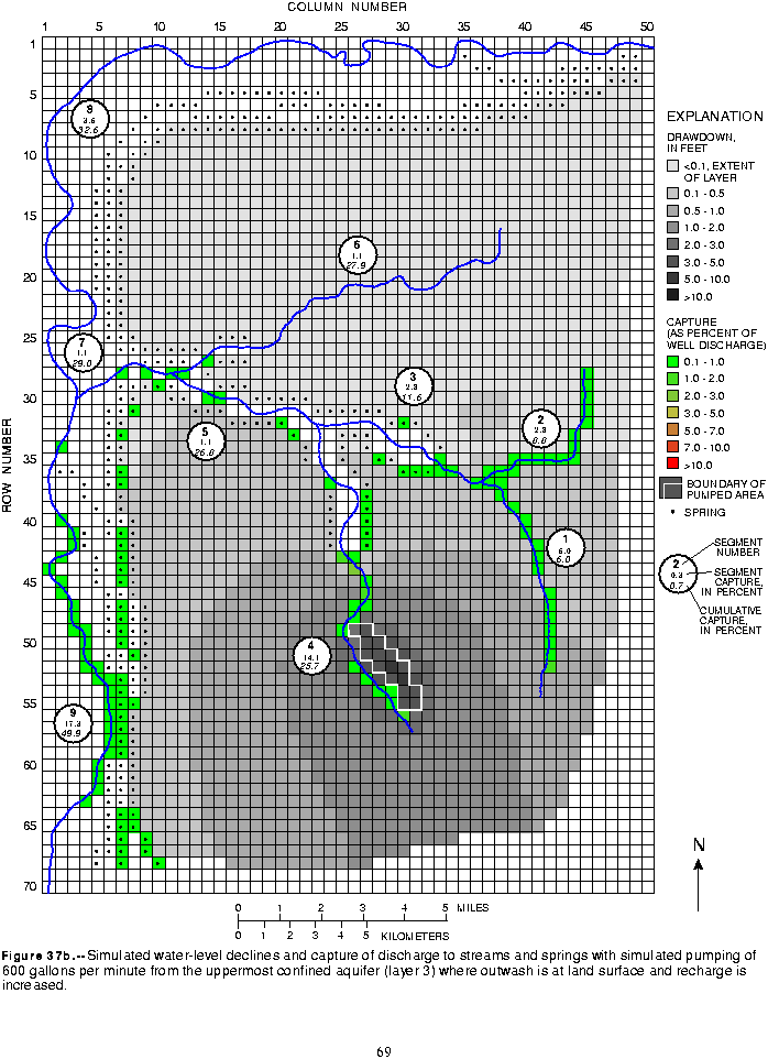
In simulations RECH.3, RECH.4, and RECH.6, the wells pumped from the uppermost confined aquifer where it is overlain by a till layer and a recessional outwash aquifer. Reducing the natural recharge rate of 27 in/yr by 27 percent over the 1.3 mi2 area of development resulted in an effective reduction of recharge of about 300 gal/min. Combined with the well pumping rate of 600 gal/min, the effective discharge from the system was 900 gal/min. Because of their locations, these wells captured a large percentage of their discharge from baseflow to stream segment 4. The primary reason was that the outwash aquifer provided discharge to the stream, and pumping the wells induced a stronger downward vertical hydraulic gradient and greater flux from the surficial outwash aquifer, through the till, to the pumped aquifer. Figure 34 shows that there are slight differences between the reduced and natural recharge simulations, but the relative sources of water to the wells are similar. Due to the difference in effective discharge rates for the reduced and natural recharge simulations, the rates of capture are not the same even though the percentages are similar.
With reduced recharge (RECH.3, fig. 37a), pumping in the area underlain by outwash resulted in less simulated drawdown than pumping in the area underlain by till (RECH.1, fig. 35a). Pumping from the aquifer underlying the unconfined aquifer adjacent to the stream had a significant effect on the upper reaches of segment 4; several reaches had baseflow reduced by 5 to 10 percent of the effective discharge rate of 900 gal/min and a total of 61 percent, or 550 gal/min, was captured from baseflow to segment 4 alone. Comparison of figures 37a and 37b shows that increasing recharge, and thus decreasing the effective discharge from 900 to 300 gal/min, greatly attenuated the effects of pumping on individual stream reaches and springs. The effect of increased recharge on the drawdown distribution is illustrated by the cumulative drawdown areas shown on figure 36. Increasing recharge in the area covered by outwash resulted in greater reductions in the effective discharge rate; the rate was reduced from 900 to 300 gal/min in the outwash area, compared with a reduction from 800 gal/min to 300 gal/min in the till area. In spite of this, the simulation results show that effects on discharge to streams and springs were attenuated when recharge was increased in the till area. As an index of the change in drawdown caused by increasing recharge in each area, the AOI for pumping in the outwash area decreased by 20 mi2, compared with the 36 mi2 decrease for pumping from the till area (fig. 36).